Network Usage
Networks are used for a number of reasons, one way or another it’s usually about sharing:
- Information: we use networks for applications like e-mail or to reach certain websites.
- File sharing: we need a network so that users can reach a shared network drive with documents, pictures and/or other files.
- Resource sharing: we can connect a printer to the network that is used by multiple users. No need to connect a printer directly to each computer.
- Application sharing: we might have users that require access to the same application. For example, a finance department with five users that need access to the same bookkeeping software.
Host
Host devices are the devices that are used by end users. A decade ago, we mostly used desktop computers but nowadays we have laptops, smartphones, and tablets.
Server
Servers are similar to computers but have a different role in the network. For example, when you check your e-mail your client is connecting to an e-mail server to fetch your e-mail. This email server might be used by thousands of users so it has to be available 24/7.
Servers use similar hardware as what you will find in computers but depending on their task, are more reliable. They have more RAM (memory) with error correction, use hard disks that were designed to be always-on, have more storage space and so on.
Servers use similar hardware as what you will find in computers but depending on their task, are more reliable. They have more RAM (memory) with error correction, use hard disks that were designed to be always-on, have more storage space and so on.
Network Interface Card
To connect our computers and servers to a network, there has to be some interface. We use NICs (Network Interface Card) for this. In laptops, tablets, and smartphones you will find wireless NICs with radios/antennas.
Communication Links
There are different types of communication links and cables. On your local network, you probably have seen UTP cables before:
For Internet connectivity, you might use DSL which uses the phone line from the telco, or perhaps you have cable Internet access which uses the COAX cable like your TV. For long distance links, a lot of fiber cable is used.
Nowadays we also use a lot of wireless technology where we use radios, antennas and radio waves for communication.
Switches
On local networks we typically use switches to connect computers and servers to the network, allowing them to communicate with each other. These switches can be as small as the one below, something you might find at home or at a small company network.
Routers
Routers are used for a number of reasons. The main reason is that they figure out what path to use to get to a certain destination. For example, you might live in New York but the e-mail server you use to check your e-mail is located in Los Angeles. Just like there are many different roads to take if you want to drive from New York to Los Angeles, there are many different network paths to take in order to send our network traffic from A to B.
By exchanging information about networks between different routers, we are able to calculate a path to get to each destination. Routers can be as small as something we use at home or at a small business
By exchanging information about networks between different routers, we are able to calculate a path to get to each destination. Routers can be as small as something we use at home or at a small business
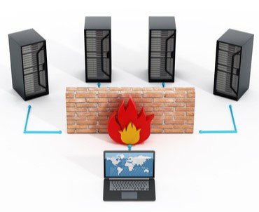
Firewalls
In a perfect world, we could trust everyone and we don’t have to worry about security. Unfortunately, besides all the great things the Internet offers us there is also a lot of malicious stuff. Think of viruses, malware, and hackers.
Firewalls are used to inspect network traffic and drop malicious traffic. We also use them to encrypt network traffic so that remote workers can access applications on the company network in a secure way.
OSI Model
In the beginning, the development of networks was chaotic. Each vendor had its own proprietary solution. The bad part was that one vendor’s solution was not compatible with another vendor’s solution. This is where the idea for the OSI model was born, having a layered approach to networks our hardware vendors would design hardware for the network, and others could develop software for the application layer. Using an open model which everyone agrees on means we can build networks that are compatible with each other.
To fix this problem the International Organization for Standardization (ISO) researched different network models and the result is the OSI-model which was released in 1984. Nowadays most vendors build networks based on the OSI model and hardware from different vendors is compatible….excellent!
The OSI-model isn’t just a model to make networks compatible; it’s also one of the BEST ways to teach people about networks. Keep this in mind since when you are studying networking you will see people refer a lot to the OSI model. Here’s what the OSI model looks like: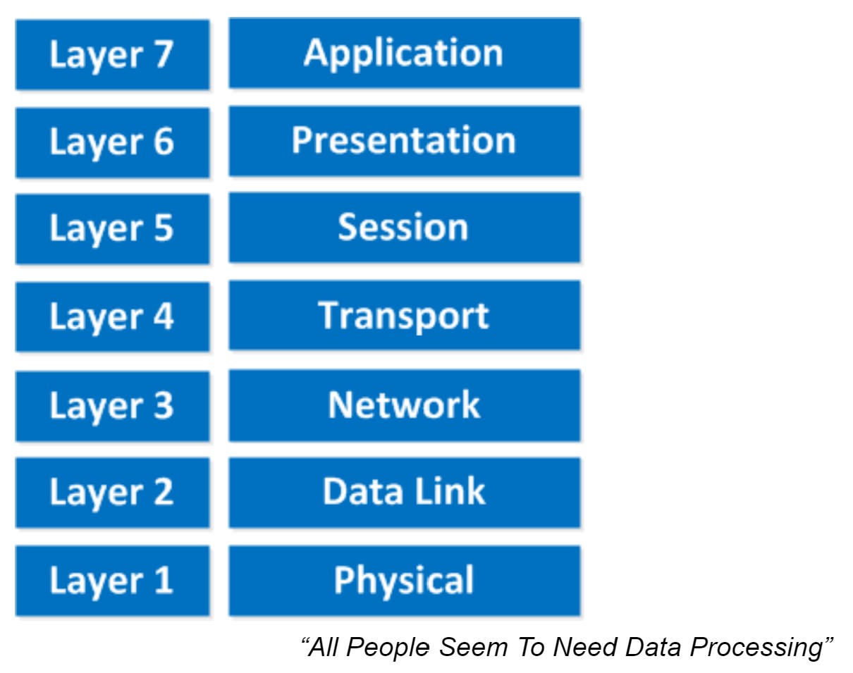 This is the OSI-model which has seven layers; we are working our way from the bottom to the top. Let’s start at the physical layer:
This one normally gives me more smiles when I’m teaching CCNA in class and it’s another way to remember the OSI-Model.
P = Physical
D = Data Link
N = Network
T = Transport
S = Session
P = Presentation
A = Application
Remember that you can’t skip any layers in the OSI-model, it’s impossible to jump from the Application layer directly to the Network layer. You always need to go through all the layers to send data over the network.
Let’s take a look at a real-life example of data transmission:
Now you know about the OSI-model, the different layers and the function of each layer. During peer-to-peer communication, each layer has ‘packets of information’. We call these protocol data units (PDU). Now every unit has a different name on the different layers:
Besides the OSI model there was another organization that created a similar reference model which never became quite as popular. When I’m talking about “not popular” I mean the TCP/IP stack model isn’t used often as a reference model…when we talk about layers, people always refer to the OSI model. On networks nowadays we use TCP/IP all the time…
Here’s what it looks like: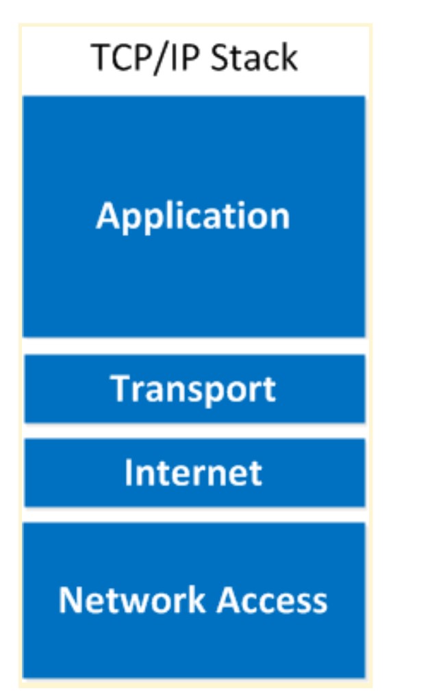 As you can see the upper three layers are now combined to the “Application layer”. The network layer is called the “Internet” layer and the bottom 2 layers are combined into the “Network Access” layer.
Here’s a comparison between the two models: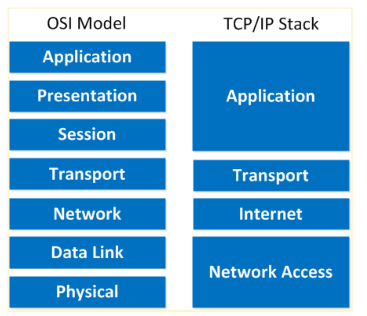 Basically it’s the same idea, same model except with some layers combined and different names. The physical and data link layer are combined into the network access layer. The network layer is now the internet layer and the session, presentation and application layer are combined into a single application layer.
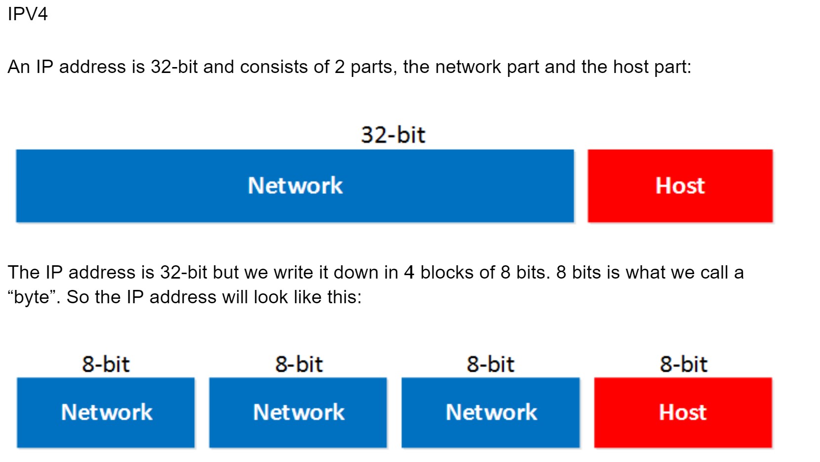 The network part will tell us to which “network” the IP address will belong, you can compare this to the city or area code of a phone number. The “host” part uniquely identifies the network device; these are like the last digits of your phone number.
You probably have seen the IP address 192.168.1.1 before. It’s a very commonly used IP address on local networks. For this IP address the first 3 bytes are the “network” address and the last byte is the “host” address: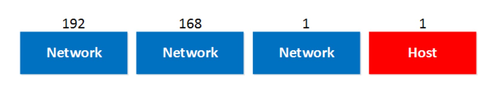 Ok awesome…but why are the first 3 bytes the “network” part and why is the last byte the “host” part? Good question! I only gave you the IP address but you might remember that if you configure an IP address you also have to specify the subnet mask. Our IP address 192.168.1.1 would come along with the subnet mask 255.255.255.0.
The subnet mask tells your computer which part is the “network” part and which part is the “host” part. Despite the name it does not “hide” or “mask” anything. We’ll talk about binary and subnetting calculations later on, for now just hold the thought that your subnet mask tells us which part of the IP address is the “network” part and which part is for “hosts”.
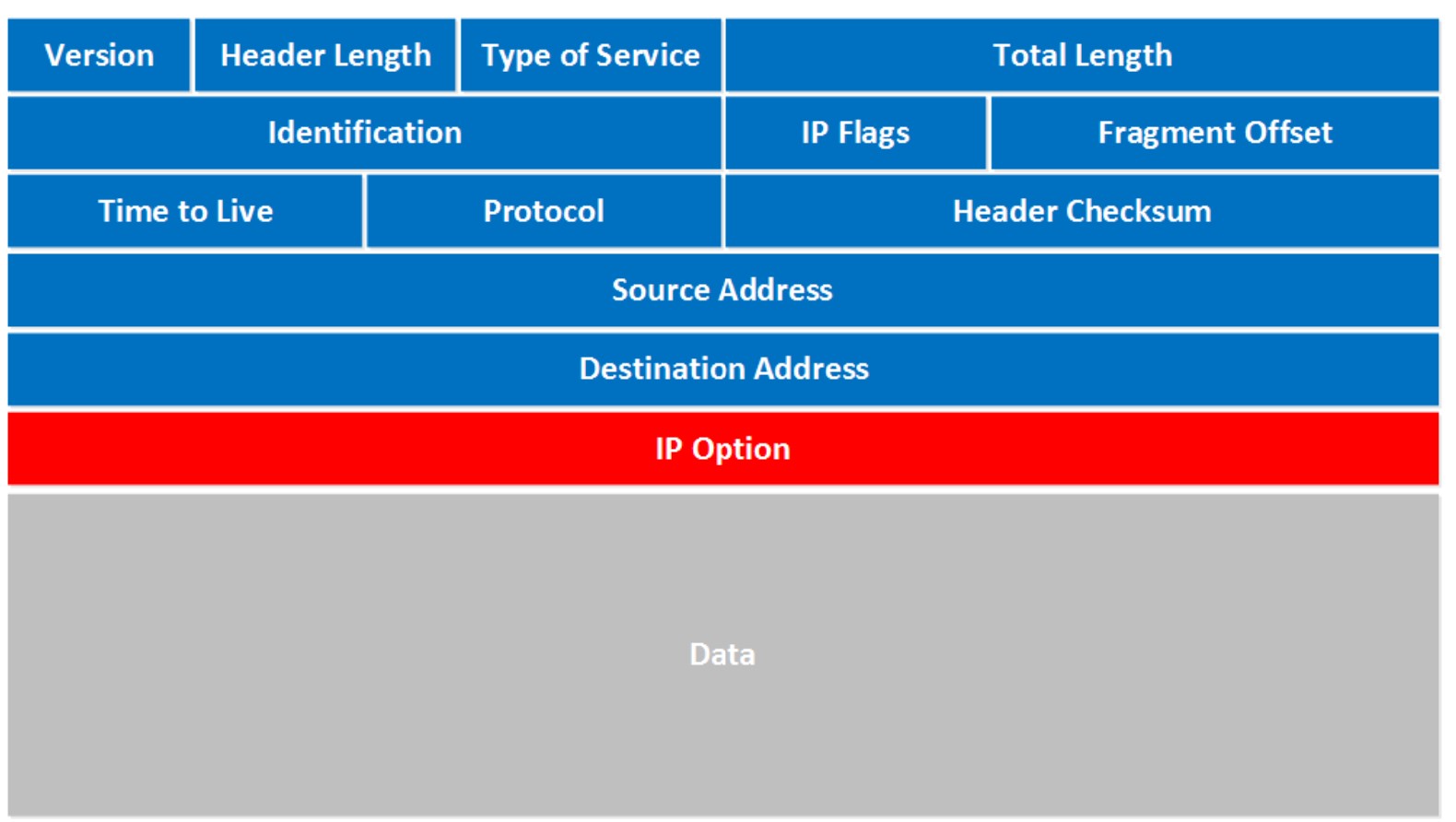
Let’s take a look at an actual IP packet: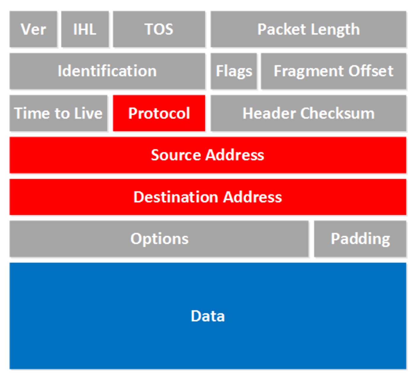 There are a lot of fields there! Now don’t go look over them and feel puzzled that you have no idea what they are about. For now there are only a few fields that are interesting to us. The fields we don’t care about are in gray, I want to focus on the red and blue fields.
To answer the second question I have to tell you that there’s actually a class D range, we don’t use those IP addresses to assign to computers but it’s being used for “multicast”. It starts with the 224.0.0.0 range.
The last thing I need to tell you about classes is the difference between “private” and “public” IP addresses.
The broadcast address cannot be used on a computer as an IP address because it’s used by broadcast applications. A broadcast is an IP packet that will be received by all devices in your network.
So how do we recognize these two IP addresses that we cannot use? Let me give you an example for this: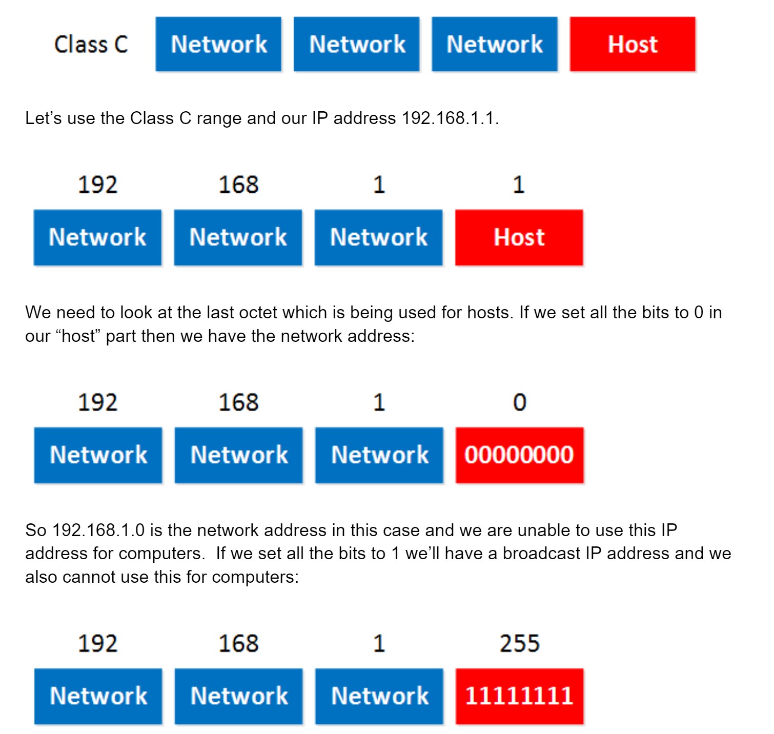 So in summary:
To fix this problem the International Organization for Standardization (ISO) researched different network models and the result is the OSI-model which was released in 1984. Nowadays most vendors build networks based on the OSI model and hardware from different vendors is compatible….excellent!
The OSI-model isn’t just a model to make networks compatible; it’s also one of the BEST ways to teach people about networks. Keep this in mind since when you are studying networking you will see people refer a lot to the OSI model. Here’s what the OSI model looks like:
This is the OSI-model which has seven layers; we are working our way from the bottom to the top. Let’s start at the physical layer:
- Physical Layer: This layer describes stuff like voltage levels, timing, physical data rates, physical connectors and so on. Everything you can “touch” since it’s physical.
- Data Link: This layer makes sure data is formatted the correct way, takes care of error detection and makes sure data is delivered reliably. This might sound a bit vague, but for now, try to remember this is where “Ethernet” lives. MAC Addresses and Ethernet frames are on the Data Link layer.
- Network: This layer takes care of connectivity and path selection (routing). This is where IPv4 and IPv6 live. Every network device needs a unique address on the network.
- Transport: The transport layer takes care of transport. When you downloaded this lesson from the Internet the webpage was sent in segments and transported to your computer.
- TCP lives here; it’s a protocol which sends data in a reliable way.
- UDP lives here; it’s a protocol which sends data in an unreliable way.
- Session: The session layer takes care of establishing, managing and termination of sessions between two hosts. When you are browsing a website on the internet you are probably not the only user of the webserver hosting that website. This webserver needs to keep track of all the different “sessions”.
- Presentation: This one will make sure that information is readable for the application layer by formatting and structuring the data. Most computers use the ASCII table for characters. If another computer would use another character like EBCDIC then the presentation layer needs to “reformat” the data so both computers agree on the same characters.
- Application: Here are your applications. E-mail, browsing the web (HTTP), FTP and many more.
This one normally gives me more smiles when I’m teaching CCNA in class and it’s another way to remember the OSI-Model.
P = Physical
D = Data Link
N = Network
T = Transport
S = Session
P = Presentation
A = Application
Remember that you can’t skip any layers in the OSI-model, it’s impossible to jump from the Application layer directly to the Network layer. You always need to go through all the layers to send data over the network.
Let’s take a look at a real-life example of data transmission:
- You are sitting behind your computer and want to download some files of a local webserver. You start up your web browser and type in the URL of your favorite website. Your computer will send a message to the web server requesting a certain web page. You are now using the HTTP protocol which lives on the application layer.
- The presentation layer will structure the information of the application in a certain format.
- The session layer will make sure to separate all the different sessions.
- Depending on the application, you want a reliable (TCP) or unreliable (UDP) protocol to transfer data towards the web server. In this case, it’ll choose TCP since you want to make sure the webpage makes it to your computer. We’ll discuss TCP and UDP later.
- Your computer has a unique IP address (for example 192.168.1.1) and it will build an IP packet. This IP packet will contain all the data of the application, presentation and session layer. It also specifies which transport protocol it’s using (TCP in this case) and the source IP address (your computer 192.168.1.1) and the destination (the web server’s IP address).
- The IP packet will be put into an Ethernet Frame. The Ethernet frame has a source MAC address (your computer) and the destination MAC address (web server). More about Ethernet and MAC addresses later.
- Finally, everything is converted into bits and sent down the cable using electric signals.
- First, you write a letter.
- You put the letter in an envelope.
- You write your name and the name of the receiver on the envelope.
- You put the envelope in the mailbox.
- The content of the mailbox will go to the central processing office of the postal service.
- Your envelope will be delivered to the receiver.
- They open the envelope and read its contents.
Now you know about the OSI-model, the different layers and the function of each layer. During peer-to-peer communication, each layer has ‘packets of information’. We call these protocol data units (PDU). Now every unit has a different name on the different layers:
- Transport layer: Segments; For example, we talk about TCP segments.
- Network layer: Packets; For example, we talk about IP packets here.
- Data link layer: Frames; For example, we talk about Ethernet frames here.
Besides the OSI model there was another organization that created a similar reference model which never became quite as popular. When I’m talking about “not popular” I mean the TCP/IP stack model isn’t used often as a reference model…when we talk about layers, people always refer to the OSI model. On networks nowadays we use TCP/IP all the time…
Here’s what it looks like:
As you can see the upper three layers are now combined to the “Application layer”. The network layer is called the “Internet” layer and the bottom 2 layers are combined into the “Network Access” layer. Here’s a comparison between the two models:
Basically it’s the same idea, same model except with some layers combined and different names. The physical and data link layer are combined into the network access layer. The network layer is now the internet layer and the session, presentation and application layer are combined into a single application layer.
The network part will tell us to which “network” the IP address will belong, you can compare this to the city or area code of a phone number. The “host” part uniquely identifies the network device; these are like the last digits of your phone number. You probably have seen the IP address 192.168.1.1 before. It’s a very commonly used IP address on local networks. For this IP address the first 3 bytes are the “network” address and the last byte is the “host” address:
Ok awesome…but why are the first 3 bytes the “network” part and why is the last byte the “host” part? Good question! I only gave you the IP address but you might remember that if you configure an IP address you also have to specify the subnet mask. Our IP address 192.168.1.1 would come along with the subnet mask 255.255.255.0. The subnet mask tells your computer which part is the “network” part and which part is the “host” part. Despite the name it does not “hide” or “mask” anything. We’ll talk about binary and subnetting calculations later on, for now just hold the thought that your subnet mask tells us which part of the IP address is the “network” part and which part is for “hosts”.
Let’s take a look at an actual IP packet:
There are a lot of fields there! Now don’t go look over them and feel puzzled that you have no idea what they are about. For now there are only a few fields that are interesting to us. The fields we don’t care about are in gray, I want to focus on the red and blue fields.
- Protocol: Here you will find which protocol we are using on top of IP, this is how we specify which transport layer protocol we are using. So you’ll find TCP, UDP or perhaps something else in here.
- Source Address: Here you will find the IP address of the device that created this IP packet.
- Destination Address: This is the IP address of the device that should receive the IP packet.
- Data: this is the actual data that we are trying to get to the other side.
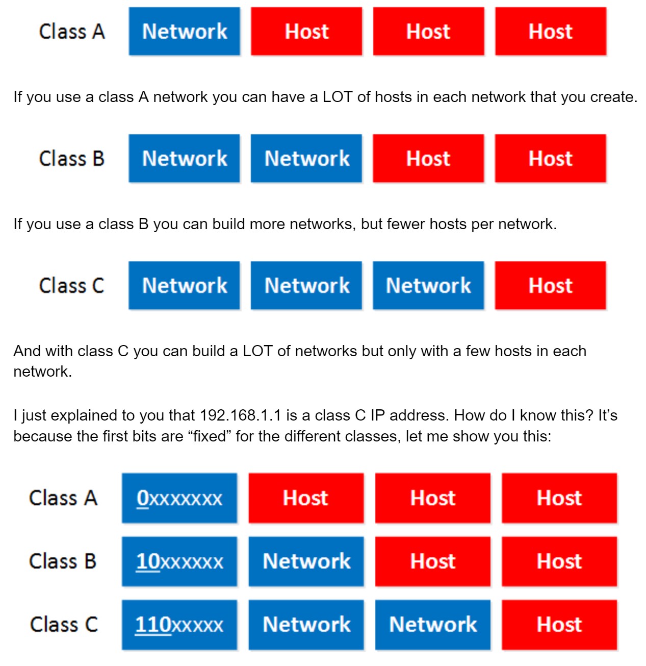
- Class A: The first bit always has to be 0.
- Class B: The first 2 bits always have to be 10.
- Class C: The first 3 bits always have to be 110.
- Class A starts at 0.0.0.0
- Class B starts at 128.0.0.0
- Class C starts at 192.0.0.0
- Class A: 0.0.0.0 – 126.255.255.255
- Class B: 128.0.0.0 – 191.255.255.255
- If you look closely, do you see a 127.0.0.0 subnet? It’s not in the class A range so what happened to it?
- Why does Class C stop at 223.255.255.255?
To answer the second question I have to tell you that there’s actually a class D range, we don’t use those IP addresses to assign to computers but it’s being used for “multicast”. It starts with the 224.0.0.0 range.
The last thing I need to tell you about classes is the difference between “private” and “public” IP addresses.
- Public IP addresses are used on the Internet.
- Private IP addresses are used on your local area network and should not be used on the Internet.
- Class A: 10.0.0.0 – 10.255.255.255
- Class B: 172.16.0.0 – 172.31.255.255
- Class C: 192.168.0.0 – 192.168.255.255
- Network address.
- Broadcast address.
The broadcast address cannot be used on a computer as an IP address because it’s used by broadcast applications. A broadcast is an IP packet that will be received by all devices in your network.
So how do we recognize these two IP addresses that we cannot use? Let me give you an example for this:
So in summary:
- Set all the host bits to 0 gives you the network address.
- Set all the host bits to 1 gives you the broadcast address.
- These 2 IP addresses we cannot use for computers.
IPv4 Packet Header
The IPv4 packet header has quite some fields. In this lesson we’ll take a look at them and I’ll explain what everything is used for. Take a look at this picture:
 Let’s walk through all these fields:
Let’s walk through all these fields:
- Version: the first field tells us which IP version we are using, only IPv4 uses this header so you will always find decimal value 4 here.
- Header Length: this 4 bit field tells us the length of the IP header in 32 bit increments. The minimum length of an IP header is 20 bytes so with 32 bit increments, you would see value of 5 here. The maximum value we can create with 4 bits is 15 so with 32 bit increments, that would be a header length of 60 bytes. This field is also called the Internet Header Length (IHL).
- Type of Service: this is used for QoS (Quality of Service). There are 8 bits that we can use to mark the packet which we can use to give the packet a certain treatment. You can read more about this field in my IP precedence and DSCP lesson.
- Total Length: this 16-bit field indicates the entire size of the IP packet (header and data) in bytes. The minimum size is 20 bytes (if you have no data) and the maximum size is 65.535 bytes, that’s the highest value you can create with 16 bits.
- Identification: If the IP packet is fragmented then each fragmented packet will use the same 16 bit identification number to identify to which IP packet they belong to.
- IP Flags: These 3 bits are used for fragmentation:
- The first bit is always set to 0.
- The second bit is called the DF (Don’t Fragment) bit and indicates that this packet should not be fragmented.
- The third bit is called the MF (More Fragments) bit and is set on all fragmented packets except the last one.
- Fragment Offset: this 13 bit field specifies the position of the fragment in the original fragmented IP packet.
- Time to Live: Everytime an IP packet passes through a router, the time to live field is decremented by 1. Once it hits 0 the router will drop the packet and sends an ICMP time exceeded message to the sender. The time to live field has 8 bits and is used to prevent packets from looping around forever (if you have a routing loop).
- Protocol: this 8 bit field tells us which protocol is enapsulated in the IP packet, for example TCP has value 6 and UDP has value 17. Header Checksum: this 16 bit field is used to store a checksum of the header. The receiver can use the checksum to check if there are any errors in the header.
- Source Address: here you will find the 32 bit source IP address.
- Destination Address: and here’s the 32 bit destination IP address.
- IP Option: this field is not used often, is optional and has a variable length based on the options that were used. When you use this field, the value in the header length field will increase. An example of a possible option is “source route” where the sender requests for a certain routing path.